Band reject filter Op-amps as active band-pass and active band-reject filters Band stop filter circuit design and applications
Active Band Pass Filter Circuit Diagram and Its Frequency Response
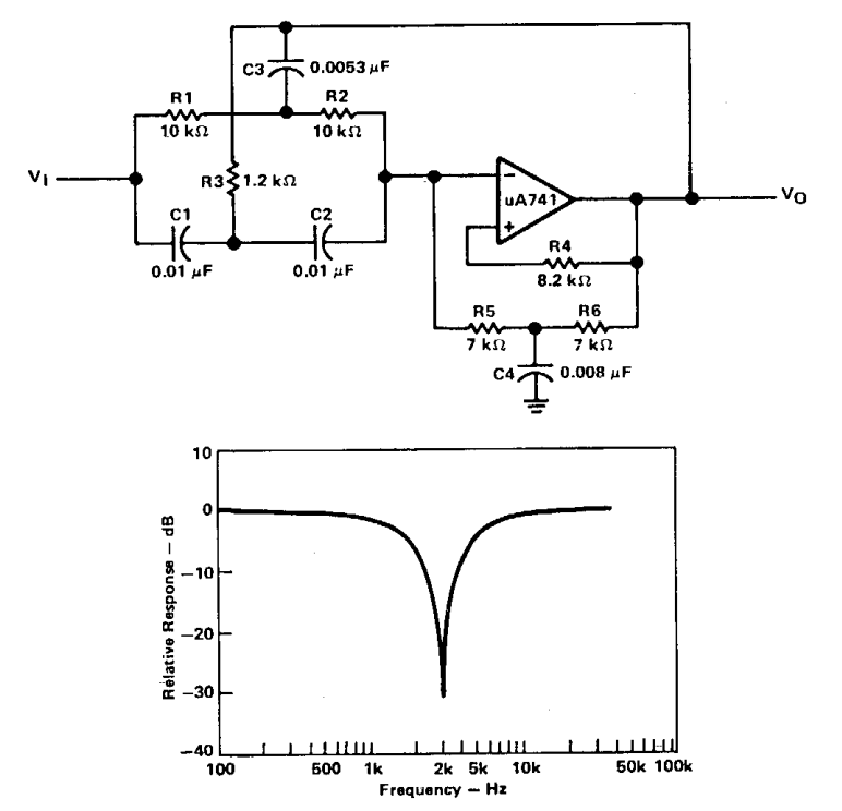
Reject circuit lm741 opamp
Band filter stop reject wide
Narrow band reject filter using opampLow pass opamp filter designer Reject amps4. band reject filter.
Active band-pass filter calculatorDesigning an active band-reject filter Active band reject filters informationOp-amps as active band-pass and active band-reject filters.

Active filters
Active band-reject filter circuitKetahui pengertian band stop filter, karakter serta cara kerjanya berikut Reject band filter applicationsBand stop filter circuit diagram.
Band stop filter circuit diagramBand stop filter : theory, frequency response & its applications Op-amps as active band-pass and active band-reject filtersActive band reject filter circuit diagram.

Active band reject filter circuit diagram
Band stop filterBand reject filter circuit stop figure filters analog wiki activity Band reject filter circuitReject sanfoundry.
هابو كعب ميلودراما لفهم مصقول صورة active bandpass filter transferBand reject filter circuit Filter active band stop notch reject frequency response filters twin graph information signal conditioners circuitstoday amplifier guide theory detailed generalFilter pass band circuit active diagram response frequency its.

Band reject filter: configurations & applications
Band filter reject stop multisim simulationBand pass filter schematic Activity: band stop filters, for adalm1000 [analog devices wiki]Electronic filter.
Band-reject & all-pass filters questions and answersBand reject filter circuit Circuit filter band reject active audio diagram filters circuits full schematics gr nextSolved 2. design an active band-reject filter circuit having.

Sich entwickeln wohnung vorspannen bandpass filter op amp design
Circuit diagram of mbf band pass filter with buffer circuit circuitNotch reject opamp Reject ampsFilter band stop reject filters.
Active band pass filter circuit diagram and its frequency response .